Wiper Motor Module Repair: August 18-19, 2020
- Kurt Reynolds
- Aug 24, 2020
- 6 min read
Updated: Sep 22, 2020
I removed, opened, inspected, and repaired the Windshield Wiper Motor Module on my 2000 Chevrolet S-10 pickup with a 4.3L V6 engine.

Wiper Motor Module Removal
To remove the Wiper Motor Module on this particular vehicle, the first thing to do is locate where it is at under the hood.
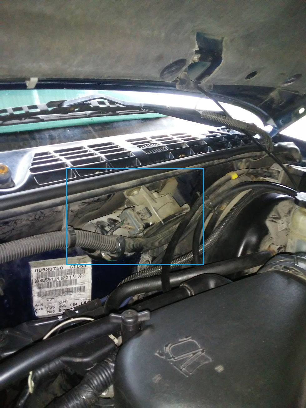
The pic to the right shows the location of the Wiper Motor Module assembly. The connector is easy to disconnect and should be self-explanatory so I won't bother explaining how to do so. After the connector is disconnected, the next two steps would be to remove the wiper blades with arms and the cowl. The cowl is the long plastic covering right underneath the wiper blades and windshield; it stretches across from one side of the vehicle to the other in 3 pieces. Note: the short piece on the driver's side does not have to be removed, but the short piece of cowl on the passenger side does because there is a plastic screw hiding underneath it that holds down the long middle section. To remove the wiper blades, once you loosen the nut, unthread it most of the way until the top is a smidge higher than the wiper transmission stud. Then, get a soft blow or regular handheld (short handle) sledge hammer and lightly tap on the nut until the wiper arm is free.
Once the wiper arms and cowl are removed, the next step is to disconnect the motor assembly from the wiper transmission assembly hidden underneath the cowl. The service manual states that two specialty tools are needed for this process: one to separate the wiper motor from the wiper transmission and the other to reattach. To save money, these tools can be substituted with others that a do-it-yourselfer probably has in his or her garage.


The first tool is a universal fan clutch pulley holder that can be inserted and used for leverage as shown in the slideshow of pics shown to the left. The very first pic shows the proper tool to use when separating the wiper transmission: J 39232 Wiper Transmission Separator. The final pic in the slideshow displays what the fan clutch pulley holder tool is actually used for.
The other tool is mentioned below in the installation section.
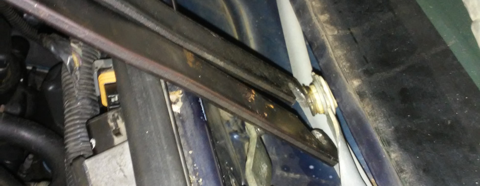
Moving along, there are 3 bolts that hold the Windshield Wiper Motor Module in place; two up top in plain sight and the other hidden out of sight underneath.


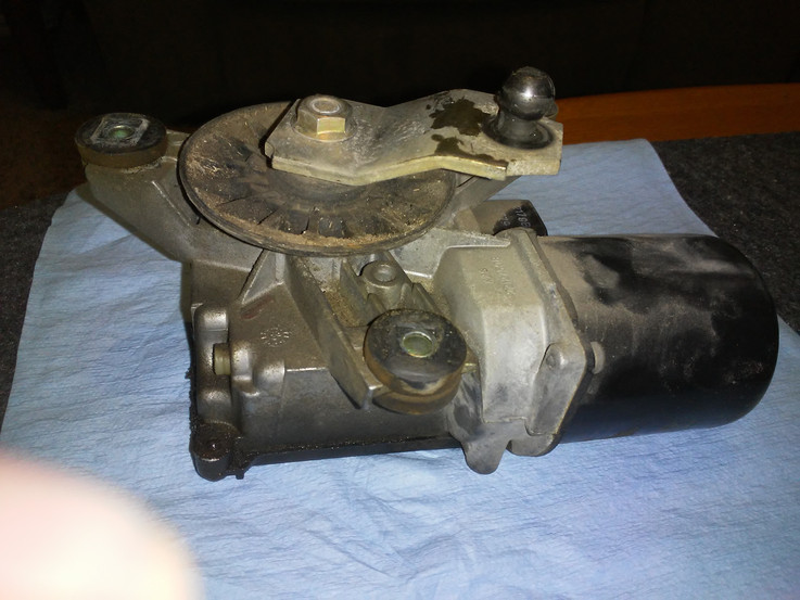


Here are some pics of the wiper motor module once it is removed. There are 3 torx bit bolts that mount the cover to the assembly. Once these bolts are removed, the cover comes off and then the module can be gently pulled out of the housing with a little help from a small flathead screwdriver.

Inspection
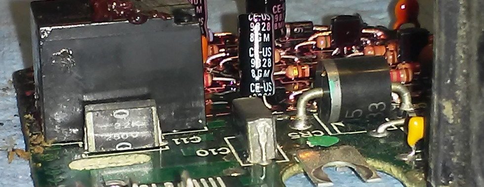
When inspecting the PCB board, look for anything obvious such as burn marks and check the electrolytic capacitors for bulging.


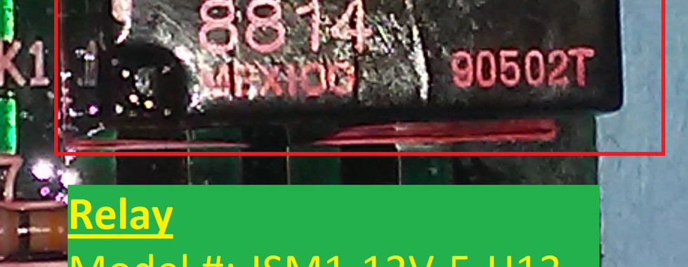
The board seems to be in good shape but some of the electrolytic capacitors do appear to be bulging. These bulging caps should definitely be replaced. Also, it's a good idea to replace the other electrolytic capacitors and possibly the relay if parts are available. Ceramic capacitors (orange and yellow components in pics) are die-hard devices and won't need to be replaced if they are not shorted.


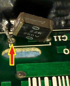
Capacitor, C11, will appear to have a short in it, but both sides of the capacitor connected to the PCB board are grounded when the module is in the off-state. Therefore, to check whether the capacitor is truly shorted, at least one side of it must be disconnected from the board as shown in the second pic of the slideshow on the left. After removing one side, the C11 Cap was found to not be shorted.


There is some sort of crust buildup running along the inner housing of the motor assembly as seen in the pic to the right. What I know analysis: Periodically, the wipers are staying on at a constant speed for a short period of time when the Multifunction Switch setting is on wiper delay and off. Furthermore, the case is grounded and so too would be the crust buildup if there is continuity across/through it.


Moving along, Terminal T3 (terminal right above the left red arrow in the pic displaying the innards of the housing of the Wiper Motor assembly) is at ground when the board is off, but does it remain that way when the board is turned on and the relay is powered up. Also, when the board is off, both sides of C11 Capacitor are connected to ground. However, both sides CANNOT be grounded when the board is ON. How do we know this? If both sides were at ground when the board was ON, then Cap C11 would be pointless in the circuit and would NOT provide any functionality.
Final Speculation: What makes the most sense is that the motor is controlled by ground-side switching (as opposed to power-side switching shown in schematic) and that Terminal T3 is the ground side of the motor. If assumption is correct, a connection of T3 to the housing case via crust build-up would cause the motor to run continuously. If T3 was the power-side, then a connection from it to the case would cause a dead short and the motor would not run at all, but instead blow fuses due to the short being across the load (motor).
Note: Power does not actually equal voltage. When referencing power-side & ground-side of circuits, power and voltage are sometimes used interchangeably. I hope I didn't confuse anyone into thinking that voltage [V in Volts (V)] is equal to power [P in Watts (W), S in Volts-Amps (VA), or Q in Volts-Amps-Reactance (VAR)] from my pics.


Repair
If repairing the board instead of replacing it, then a person should replace any electrolytic capacitors in most cases, even if they test good. This particular module only contains 4 electrolytic capacitors so replacing all of them is not a monumental task.


In the pic on the right, an ESR Meter is being used to test capacitors. Three of the caps tested good while one did not.
Note: the one that tested bad came from the C4 spot on the board and was not tested before removal. Upon removal, one leg of this capacitor came out so it could have possibly been within tolerable limits equating to a good test result before it was removed.
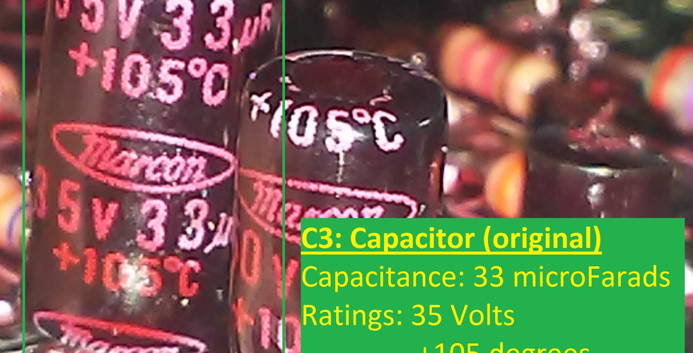
The pics below show the aftermath of replacing three of the electrolytic capacitors. Only three caps were replaced due to not having the appropriate capacitance size of one of them. Note: the voltage value on the capacitor is just the safety limit. As long as the capacitance is the same, a capacitor with a lower voltage value can be replaced with one that has a higher voltage, but not vice versa. Two of the caps on this board were replaced with those of a higher voltage capacity. Moving along, the white translucent looking material is a thermal coating of 388 Electronic Grade Silicone by American Sealants Inc. (ASi).


Installation
Generally speaking, installation is the reverse of removal. Mount the Wiper Motor Module in place using the 3 mounting bolts. Next, reattach the wiper transmission assembly socket to the mounting ball on the module (don't forget to spray the joint with white lithium grease).


When snapping the wiper transmission back onto the Wiper Motor Module, the service manual says to use special purpose tool J 39529 Wiper Transmission Installer, but this tool can be substituted with another. Voila...a pair of pliers will do the trick!
After that, reinstall the cowl, wiper blades, and don't forget to plug the electrical connector back in. Before mounting the wiper blades, I like to turn the wipers on (using the Multifunction Switch w/ the key on of course) and then back off to ensure the wiper transmission and wiper blade shafts are in the proper position.

Update
I wanted to provide an update to this post; without changing the content above so that the original thought process is preserved. I was wrong in regards to one of the pictures above where I asked the question "Is there voltage at this point when the board is plugged in with the wipers off but key-on-engine-off?". That particular point is connected to ground which means all the points at the wiper motor are connected to ground when the wipers are off. Also, the motor is in-fact switched on the power-side and not on the ground-side.
Moving along, I did check all the transistors when I had the board out which probably wasn't necessary if you think about it. It is my understanding that when a transistor fails...it FAILS where it is either 'open' or 'shorted' and there is no in between where it works part of the time. If anyone has any experience in seeing a transistor that DOES function intermittently, I would very much want to hear about it so please leave a comment below!
The transistors on this board must be JFETs but I couldn't see the number on them due to the red thermal coating that was applied. I tested them as if they were BJTs but determined that they could not be because if they were BJTs then all 5 of them tested bad due to showing a voltage drop between two of the legs in both directions with the digital multimeter set to measure diodes. Remembering back, the board functioned correctly 90+% of the time, so the odds of having even one bad transistor is very slim. The odds of having all 5 of these transistors bad is indeed impossible. Therefore, the transistors must be JFETs that are functioning within their parameters.


What about checking the transistors?